Radioberry juice journey continues….
There was still a road ahead for the development of the juice board.
I2C supported by radioberry gateware
One of the things to discover was the i2c connection.
As reported in the previous post the juice board using the FT-245 protocol is
not able to use the i2c MPPSE mode of the FT2232 FTDI chip. To make use of bus for controlling the radioberry preamp the i2c logic must be build into the gateware.
During the development of the preamp i added an additional parallel i2c bus.
This i2c bus can now be used for the i2c controlled from the FPGA
https://github.com/pa3gsb/Radioberry-2.x/wiki/Radioberry-In-Output
(pin 15 and pin 16 of the radioberry io connector)
The HL-2 hardware uses 3 i2c busses:
- Slow 4 channel ADC
- Programmable clock generator (not used in radioberry)
- Digital Pot and  N2ADR filter selection
All controlled by the gateware.
Radioberry uses one i2c bus containinng the following devices:
- Slow 4 channel ADC
- Digital Pot

both i2c devices present at preamp board

- N2ADR filter selection
The slow ADC is used to measure the bias current, temperature of the PA finals, FWD and REV voltages.
Setting up the BIAS of the finals is done by the digital pot; the setup is kept in the EEPROM of the digital pot.
The gateware is modified to make this possible.
In the change also the RQST functionality; which Steve defined as an addtion to the original openHPSDR protocol-1, is implemented.
All described in the protocol:
https://github.com/softerhardware/Hermes-Lite2/wiki/Protocol
for the HL-2.
The gatware must responds within a certain time… quisk and wireshark were very helpfull in testing.
It took some development effort (at least for me) to get it working properly, without quisk complaining; the quisk code was helping in the process to understand how it all should work!
The protection of the PA finals is also included in the gateware using the juice board. If the temperature is too high, following the same temperature as defined for the HL-2, the PA is shutdown.
Also implememted the PWM for a fan; but not yet assigned the pwm to a FPGA output pin!
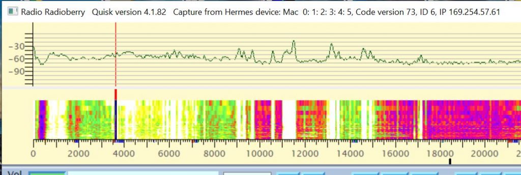
Bandscope
Also the bandscope is working. Useable from Quisk and linHPSDR.
Setup configuration
The following overview shows what is possble with the juice board.
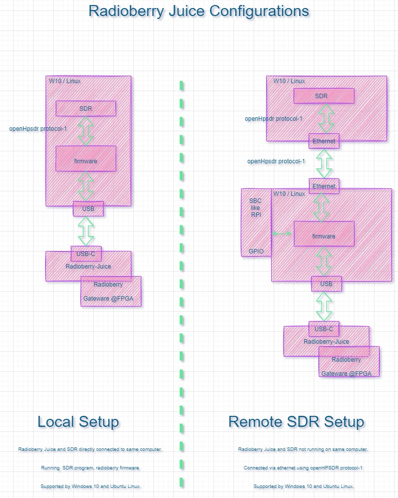
Nice to see that it is possible to use different machines and platforms.
The firmware provides in:
- loading gateware into radioberry FPGA
- openHPSDR protocol-1 (Discovery, IQ streaming and control)

When the firmware is running on a RPI or other SBC the GPIO can be used.
My Setup
I took some time searching for a computer for running the radioberry together with the juice board.
Decided to go for a Refurbished mini pc
ThinkCentre M900
Processor:Intel Core i5
Processor type:i5-6500T CPU @ 2.50GHz
Internal 8GB
Dimensions (W x D x H)
(inches) : 1.36″ x 7.20″ x 7.05″
(mm) : 34.5 x 182.9 x 179
6* USB 3.0
Audio in and out.
Making the computer dual boot; using W10 and Ubuntu linux.
Also a big advantage is to make use of a large computer screen; also a screen useable for normal computer work no need of additional (small) screens.
For controlling the radio i bought an MIDI controller a behringer cmd pl-1; active support to use with pihpsdr and other software!
Have fun
73 Johan
PA3GSB
Hello Johan,
I’m confused: does the juice board needs to be connected through USB or can it still be piggybacked on the RPI4?
-ben
Hi Ben
The juice board replaces the RPI. You can connect the usb cable to a computer or a RPI.
See the pictures in part 1 of the story.
Johan
PA3GSB