A development journey …
Wishes for the radioberry to improve:
- IQ bandwith increase
- CPU utilization reduction
- Supporting multiple platforms
- Different computer boards
- Easy setup
But keeping :
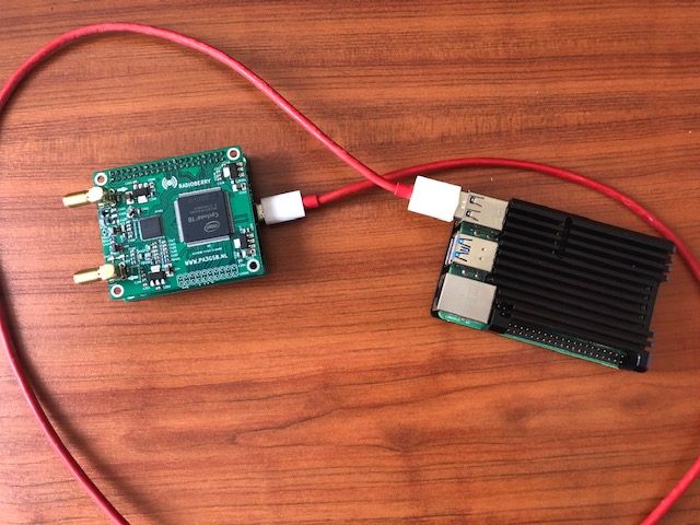
The radioberry with the high coupling to the RPI must be kept; i want to keep the charm of this radio setup.
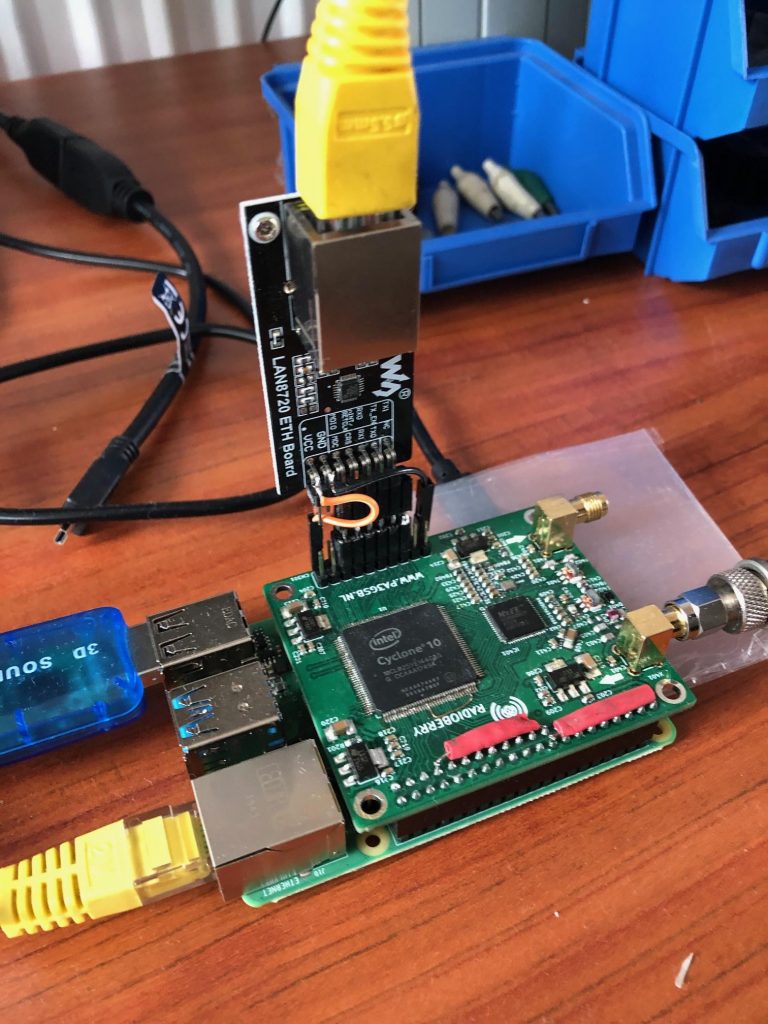
Some time ago i tried to add an ethernet module; it worked but the RPI was still needed.
In the search for all these improvemets i made a proposal for an alternative setup.
The proposal:
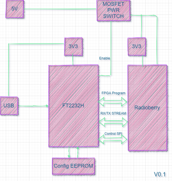
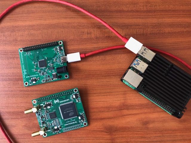
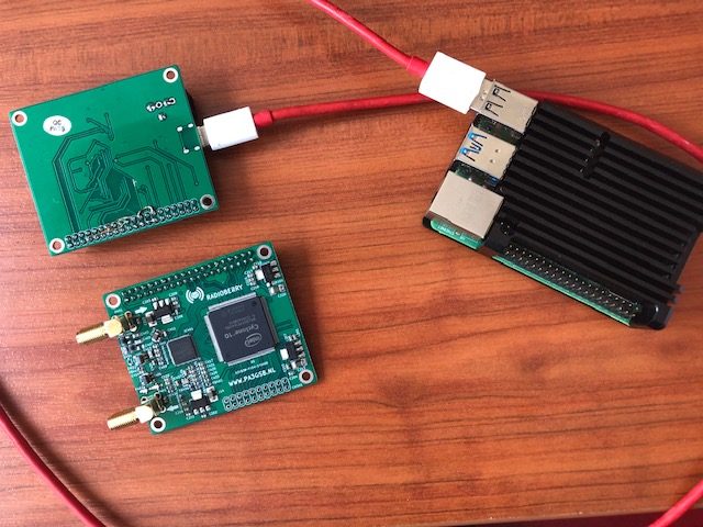
I like to introduce a Radioberry FT2232H extension board; renamed into the radioberry juice board.
This radioberry can be plugged in to the board (like you connect a RPI).
This board contains the FTDI FT2232 chip and implements an USB interface.
The extensionboard communicates with any SBC/PC via USB, making it possible to connect better performing SBC or a PC.
To allow USB communications between a PC and the FPGA,
the extension board uses an FT2232H USB device to create a communications bridge between
the PC USB interface and the FPGA.
This communications bridge splits into two channels: a programming interface
channel and a parallel 245 FIFO communications interface channel.
The programming interface uses channel B of the FT2232H to configure
the FPGA using the Intell Cyclone Passive Serial interface.
The 245 communications interface uses channel A of the FT2232H to transfer data,
either synchronously or asynchronously, over the 245 FIFO interface to and from the FPGA.
The extensionboard utilises the functionality of the Multi-Protocol Synchronous Serial Engine (MPSSE)
architecture in channel B of the FT2232H chip to adapt to the Intell Cyclone Passive Serial interface.
MPSSE is an FTDI function that allows different synchronous protocols to be configured on any available data channel.
Once the FPGA has been configured, channel B of FT2232H can be reconfigured, using MPSSE, to operate as general purpose IO pins.
The intention was to make an IQ server controlled by a SPI interface!
During development the IQ stream and SPI control as individual functions were working fine.
In the radio setting where both functions should work together i got a problem…..took me some time to figure this out!
Sometimes it is better to read the datasheet than just doing….
Quoted from the datasheet;
‘In this mode (FT245 Style Synchronous FIFO Interface) the ‘B’ channel is not available as all resources have been switched onto channel A.’
So no SPI / I2C; no control using the FT2232H chip.
So back to the drawing board….
Can we solve this? and make it even beter as the initial proposed solution?
One big drawback in the previous solution was that i had a shortage of pins… so the
data in the synchronous mode was based on 4 data lines…. already thinking of a hardware upgrade of the
radioberry…. but that is not longer required in the next iteration of the design.
The solution is simple… looking to the HL-2 there is also 1 data channel for getting the iq datat and
control data from and to the SDR program….
i will follow the same principal.
In the gateware i have only to reimplement the usopenhpsdr1.v and dsopenhpsdr1.v and making
a module for the physcial interface.
Making the phy interface in verilog… i had some problems to solve…
After sending 510 bytes i lost 2 bytes! Took me sometime to figure this out! Seems that the FTDI is using 2 bytes
for controlling the USB bulk stream (which is 512 bytes);
So i learned when checking for speed you also must look to data integrity…
The advantage is that the gateware is now implementing the protocol 1 packets… which can be easliy
placed, using one line c code in the ethernet package :
………….
read_stream(hpsdrdata); // fetching 1032 bytes of ethernet packet.
………….
in stead of building the p-1 packet in the c code.
example from the firmware using the radioberry driver running at a RPI:
void fillPacketToSend() {
	memset(hpsdrdata,0,1032);
	memcpy(hpsdrdata, header_hpsdrdata, 4);
	hpsdrdata[4] = ((last_sequence_number >> 24) & 0xFF);
	hpsdrdata[5] = ((last_sequence_number >> 16) & 0xFF);
	hpsdrdata[6] = ((last_sequence_number >> 8) & 0xFF);
	hpsdrdata[7] = (last_sequence_number & 0xFF);
	last_sequence_number++;
	memcpy(hpsdrdata + 8, sync_hpsdrdata, 8);
	memcpy(hpsdrdata + 520, sync_hpsdrdata, 8);

	if (lnrx != nrx) usleep(1000);

	lnrx = nrx;

	int factor = (lnrx - 1) * 6;
	for (int frame = 0; frame < 2; frame++) {
		int coarse_pointer = frame * 512; // 512 bytes total in each frame

		int nr_samples = (nrx == 1)? 63 : (nrx == 2)? 72: (nrx ==3)? 75: 76;
		read(fd_rb , rx_buffer , nr_samples);
		rb_sample = 0;
		for (int i=0; i< (504 / (8 + factor)); i++) {
			int index = 16 + coarse_pointer + (i * (8 + factor));
			//NR must be read from gateware.
			for (int r = 0; r < MIN(lnrx, NR); r++) {
				memcpy(hpsdrdata + index + (r * 6), rx_buffer + rb_sample, 6);
				rb_sample+=6;
			}
		}
		// inform the SDR about the radioberry control status.
		// https://github.com/softerhardware/Hermes-Lite2/wiki/Protocol

		if ( !i2c_measure_module_active & last_sequence_number % 500 == 0) read_temperature_raspberryPi();

		if ( last_sequence_number % 2 == 0) {
			// if i2c_measure_module_active; the temperature of module is used, otherwise the RPI temp.
			hpsdrdata[11 + coarse_pointer] = 0x08 | (rb_control & 0x07);
			if (i2c_measure_module_active) {
				hpsdrdata[12 + coarse_pointer] = ((pa_temp >> 8) & 0xFF);
				hpsdrdata[13 + coarse_pointer] = (pa_temp & 0xFF);
			} else {
				hpsdrdata[12 + coarse_pointer] = ((sys_temp >> 8) & 0xFF);
				hpsdrdata[13 + coarse_pointer] = (sys_temp & 0xFF);
			}
		} else {
			hpsdrdata[11 + coarse_pointer] = 0x10 | (rb_control & 0x07);
			hpsdrdata[14 + coarse_pointer] = ((pa_current >> 8) & 0xFF);
			hpsdrdata[15 + coarse_pointer] = (pa_current & 0xFF);
		}
	}
}
Making the firmware very small around 300 lines of code.
Here we are getting all the ethernet behaviour for ‘free’ no difficult coding in the FPGA.
What is done:
- inital version of firmware running at windows and linux.
- initial version of gateware for 6 RX and 1 TX
Todo:
- no i2c support yet…for the radioberry preamp board
- no i2c support for radioberry extensions
- when running on a SBC it could be possible to add i2c support to the firmware.
- adding i2c support to the gateware
- adding bandscope
What to expect about perfomance:
Based on a remark by Steve:
Bandwidth usage can be estimated.
Each IQ sample is 24 bits of I and 24 bits of Q data for 48 bits total.
If you realize 100Mbs, then you have 100e6/48 = 2.083 MHz total IQ bandwidth.
This is just over 5 384kHz receivers or 10 192kHz receivers.
I think you will run into RPi4 limitations processing and demodulating this much data before hitting bandwidth limitations
I have been testing the setup on a W10 latptop running 6 rx slices with a 384KHz sampling rate:
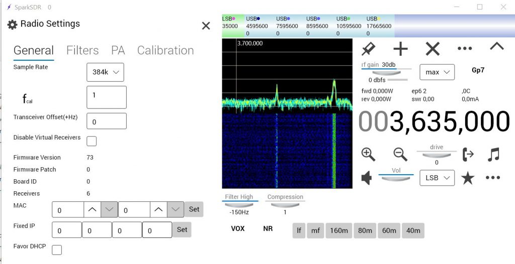
The juice board brings indeed some juice to the radioberry!
JUICE BOARD
The change of plans… makes it necessary to make a new juice board design.
Requirements for the board:
- 12 V input iso 5 V making supply mistakes (CU2ED Jacinto)
- adding a rpi pico or teensy uC ?
- i2c / spi support?
O yes a last remark:
It is also well possible to program in python… there is a nice library available for the FTDI chips.
No deadlines, all done in leisure time!
As always have fun.
73 Johan
PA3GSB
- Proposal : https://groups.google.com/g/radioberry/c/yze9Gq0Jgf8